10R Class Gallery
|
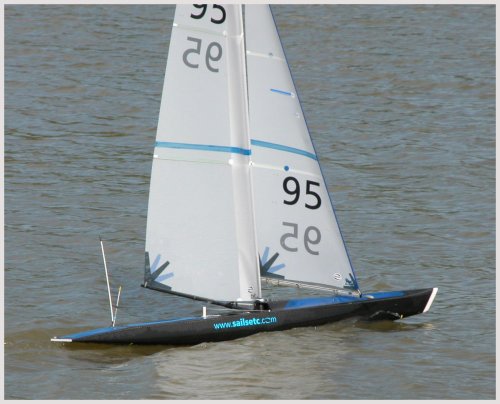
DIAMOND is the Ten Rater that SAILSetc produced from 2007 to 2014. DIAMOND has proved a successful follow up to PRIZM which took the top two places in the 1999 world championship. DIAMONDs placed 2nd and 3rd in the 2016 world championship, 2nd in 2023 and 1st and 2nd in 2025. DIAMOND has proved consitently able to provide top level perofrmance since its launch in 2006 winning th GBR, SWI, AUS, FRA, GER and ITA national championships and numerous other events too. Louis Mazet's DIAMOND shown here is one of several owned in France. No longer in production by SAILSetc or BOATSetc. Moulds possibly available to a builder able to use pre-preg materials - contact the SAILSetc office if interested. |
|
|
|
DIAMOND, like our Marblehead, has the primary hull moulding made in one piece using pre-preg carbon. This shot shows the general arrangement around the mast. The snap in/out rigging screws used on all SAILSetc production boats clip into a keyhole plate bolted over a moulded recess. The gooseneck/kicking strap unit shown here is an earlier version of the current item 12B. The primary hull moulding has recesses into which we add the headsail sheet fairleads and headsail boom swivel attachments. |
|
|
| The lower rigs normally have a pocket luff mainsail set on an un-stayed mast. The headsail boom uses the popular SAILSetc extrusion originally intended for the IOM class. The ability to adjust and re-adjust the position of everything on the boom is invaluable in setting up and tuning the rig. |
|
|
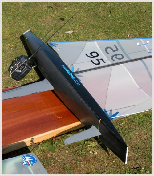
| The hull form of DIAMOND has been developed from the successful PRIZM hull form. The rocker line is quite deep at the fin where the increased hull depth adds to stability by lowering the ballast without increasing fin area. Towards the bow and stern the rocker line becomes a straight line to maximize the boat's sailing length at speed and when heeled. This also makes the boat responsive to the helm and easy to manoeuvre. The fillets (item 370LX) added to the leading edge of the fin and rudder at their interesction with the hull are standard items on SAILSetc designed boats (except SWORD). |
|
|
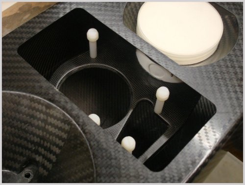
| The general layout of DIAMOND. For 2010 onwards the position and shape of the rc access hatch has been changed to this rectangular design to permit the rc pot to be placed on the centreline. |
|
|
|
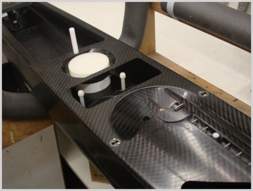
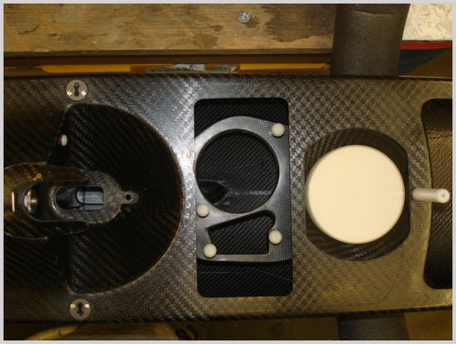
The recess for the rc pot and the special rc mount moulding are clearly shown here. An RMG280 winch is mounted on a plate and then held in place by two quick release screws. The rc mount in shaped to take the rudder servo on the port side. The recess around the mast tube allows good mechanical advantage for the gooseneck unit while keeping the mainsail luff length close to the maximum possible for a given mast length. The screw top pot lid is flush with the deck - this lowers the vcg of the pot and contents and also removes another snagging point for sheets. |
|
|
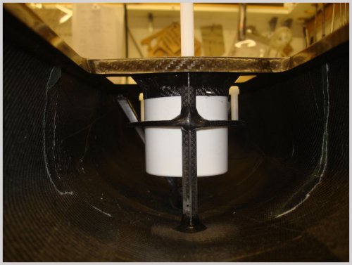
| The rc support tray is bonded onto the fin box at its front, braced by the rc pot itself and bonded to the tube in which the main sheet post is placed. The rc tray is moulded with appropriate recesses for an RMG 280 winch (or other drum winch with enough power) and a Futaba or equivalent servo. These items are held in place using our quiick release system that eliminates the need for a screwdriver. |
|
|
| Looking forward to the rc support tray, screw top pot and the carbon tube in which the main sheet post is placed. The rc pot helps support the rc tray very positively. This eliminates movement of the rudder servo relative to the hull and prevents unwanted steering effects when the winch is working hard. |
|
|
|
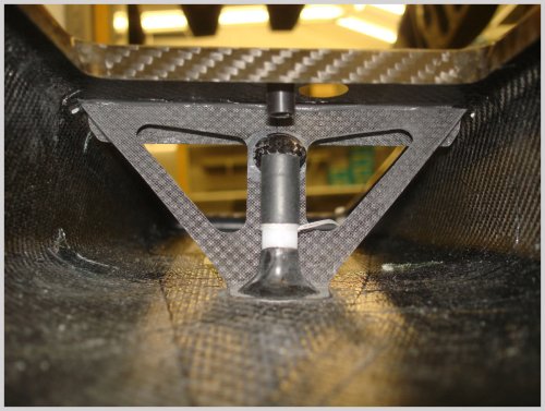
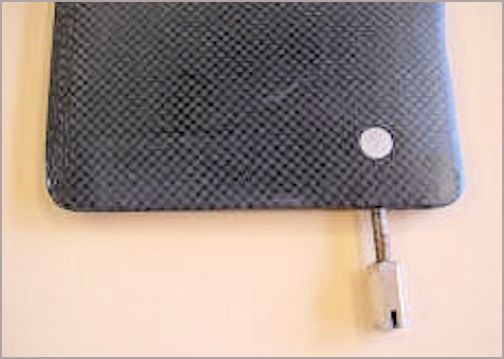
Looking aft towards the rudder trunking. This shot shows the Ten Rater but the detail is the same on the Marblehead. The white rudder trunking, item 69-040, has an 'O' ring incorporated into it to eliminate water ingress. The grip of the 'O' ring on the rudder shaft can be adjusted by tightening the upper part of the rudder trunking. A length of shrink fit tubing (black) is added to lock the parts. The line tied to the rudder trunking saves the drain bung from being lost. Directly above the rudder trunking is the upper bearing for the rudder stock. To port (right) of the upper bearing is a hole cut in the deck to give access to the tiller arm screw. Behind the rudder trunking is a special moulding that connects the bottom of the hull to the deck. The upper part of this moulding adds stiffness to the deck so that it can take the backstay loads properly. The moulding connects the hull bottom to the deck (which is the rigid part) and so the hull bottom is properly supported to. The round shape showing on that moulding is a cap that attaches the backstay fitting neatly. |
|
|
|
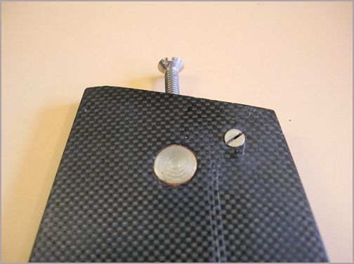
The top of the fin has a stainless steel insert bonded in place that takes the M4 stainless steel bolt used to hold the fin in place, item INS-040. Also visible at the head of the fin is the transverse M2 x 10 mm screw that we use to align the fin correctly with the hull. This permits us to correct any discrepancy in symmetry.
|
|
|
|
Likewise at the bottom of the fin we use a stainless steel insert through which M3 studding is placed, item INS-030. The fin is only about 4.8 mm thick here so there is no chance of using anyhting thicker than M3. The studding is bonded into the fin and the ballast is held in place using the long nut with a slot to allow tightening using a screwdriver.
|
|
|
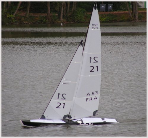
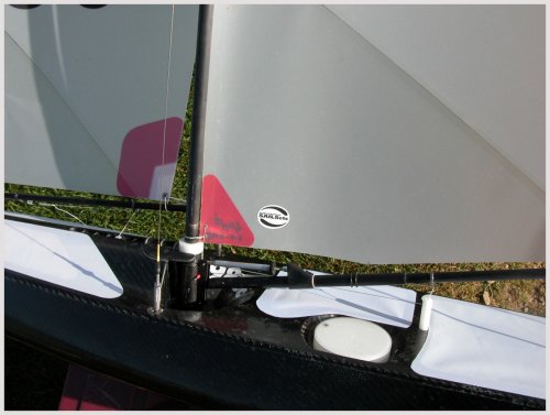 Photo by