M Class Gallery
|
QUARK is the Marblehead first made by SAILSetc in early 2013. The design follows on from PARADOX which won the 1992, 1994 and the 1998 world championships, RAD which won the 1998 world championship, and ROK which placed 2nd in the 2000 world championship, PRIME NUMBER which placed 2nd in the 2002, third in the 2006 and 2nd in the 2012 world championships. QUARKs placed 2nd, 3rd and 6th at the 2014 World Championship and 3rd in the 2016 world championship. This shot shows the original design - the current version has more freeboard at the bow and an inverted V sectioned deck. This is the boat of John Shorrock, Guildford member. Hulls, kits and completed boats are available from BOATSetc. |
|
|
|
QUARK is built using pre-preg carbon in a closed mould. This shot shows the overall layout of the centre of the boat - the join is around the line of maximum beam just below the deck level. Down turns on the edges of the deck flanges increase the stiffness of the hull structure significantly. In this shot the swing rig tube is closed off with a block that has some additional headsail sheet fairleads added as well as the mast ram. Visible also is the fairlead on the starboard deck edge where the winch line returns under deck. The mainsheet goes round a turning block (in this shot on a short lanyard) normally concealed in the bulkhead and the headsail sheet (not shown) runs through a wire fairlead just ahead of the block. The gooseneck unit is item 12B. |
|
|
|
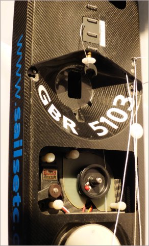
The special rc mount moulding is shown here. An RMG280 winch is mounted on a plate, item 67-280, and then held in place by two quick release screws operated by thumb and finger rather than a screwdriver. The servo is held by the same method. The rc mount is shaped to take the rudder servo on the port side. The recess around the mast tube houses the forward end of the main boom and lowers the rig into the boat. There is a neat recess for the fin bolt head. The rc pot is accessible at deck level and eliminates the need for a switch while protecting the receiver and batteries. In this shot the block through which the main sheet passes before going aft to the sheet post is recessed into the bulkhead. The headsail sheet passes through the wire fairlead just ahead of the block. |
|
|
|
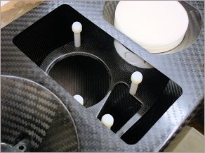
This shot shows the recess in the foredeck for the headsail swivel attachment points. The A rig headsail swivel attachment is provided by stainless steel ring on a Dyneema line attached to the bottom of a tube running down to the bottom centreline of the hull. It is just aft of the recess. Swivels for the other rigs are ball raced swivels, item 120D, mounted on SAILSetc boom material. A Dyneema line swivel at the forward end of the recess is for a Ten Rater sized No 1 rig. |
|
|
| The front end of the rc support tray is bonded onto the aft end of the fin box, braced by the rc pot itself and bonded to the tube in which the main sheet post is placed (just out of frame aft of the pot lid). The rc tray is moulded with appropriate recesses for an RMG 280 winch (or other drum winch with sufficient power) and a Futaba or equivalent servo. These items are held in place using our quick release system that eliminates the need for a screwdriver. This photo is actually of PRIME NUMBER but the layout is near identical on QUARK. |
|
|
|
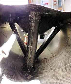
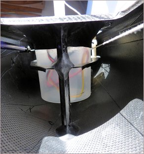
Looking aft from the bow towards the fin box and mast tube. The diagonal connections between hull bottom next to the mast and deck edge under the shroud attachment points are specially moulded items. They are not needed on a boat that will not use shrouds this saving some weight and cost. The block, spring and adjustment line used to tension the winch sheet loop is also visible. |
|
|
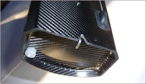
| The transom of the boat is not part of the primary hull moulding but is added afterwards. It is recessed a little into the hull and has the bung and backstay attachment point added. The through deck block, item 65-SE, where the main sheet loop exits the hull is also visible on the starboard side. |
|
|
|
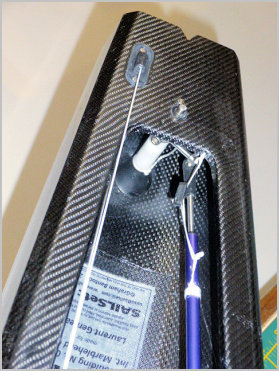
The mast ram used for the conventional rigs is a removable item that fits into a metal sleeve in the deck when required. The rectangular block with two wire fairleads for the headsail is also added at the same time and fills the hole at the top of the swing rig mast tube. The spring between the adjustment wheel and the metal sleeve prevents the adjustment wheel from moving when the boat is sailing. |
|
|
|
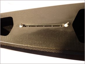
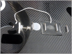
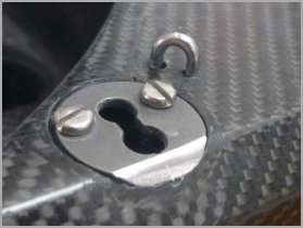
The keyhole plate that receives the quick release rigging screws, ref 31S. The ball end of the rigging screw passes into the slightly larger outboard hole and is moved across to the slightly smaller inboard hole. Once in place the rigging screw remains secure due to a combination of the rigging load from the shroud plus the compression load of a spring that is a part of the rigging screw itself. There is a small watertight cup under the plate formed as part of the primary hull moulding. The two M2 screws pass through the plate, through the cup and into the end of the moulded diagonal that connects to the bottom of the fin box/mast tube where they join the hull. This connects the loads from the shrouds to the hull structure properly and minimises flexing between fin and rig. The moulded cups (glass or carbon) and plates are availalbe as a set, item 31SET, for retro fitting to other boats. |
 |
|
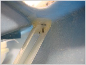
| This shot shows the connection between the upper end of the moulded diagonal and the underside of the hull/deck flange on an IOM. The diagonal is bonded in place with a stainless steel plate embedded underneath that takes the screws holding the shroud attachment plate in place. The same method is used in the Marblehead and Ten Rater. |
|
|
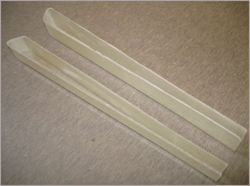
| The moulded diagonals. These are made of glass and epoxy resin but we use carbon/epoxy versions for the A Class, Marblehead and Ten Rater hulls. |
|
|
|
The way the rc pot helps support the rc mount moulding is visible here. Rigidity of the rc mount is essential if unwanted sterring effects are to be avoided when the winch is working hard. |
|
|
|
Looking aft towards the rudder trunking. The rudder trunking, item 69-040, has an 'O' ring incorporated into it to eliminate water ingress. The grip of the 'O' ring on the rudder shaft can be adjusted by tightening the upper part of the rudder trunking and a length of shrink fit tubing is added to lock the parts. The line tied to the rudder trunking saves the drain bung from being lost. Directly above the rudder trunking is the upper bearing for the rudder stock. On the starboard side is the through deck block, item 65-SE, that takes the main winch loop out of the hull. It incorporates a tiny silicone rubber seal to help keep water out. The line and bowsie connecting the deck edge flange and the tiller/servo connecting tube is a precaution to stop the rudder from over centreing and locking. |
|
|
|
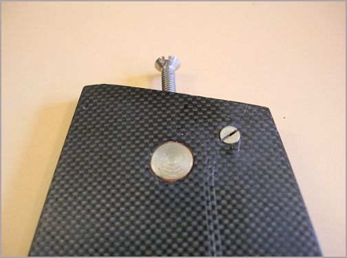
The top of the fin has a stainless steel insert bonded in place that takes the M4 stainless steel bolt used to hold the fin in place, item INS-04.0 Also visible at the head of the fin is the transverse M2 x 10 mm screw that is used to align the fin correctly with the hull. This permits correction of any discrepancy in symmetry.
|
|
|
|
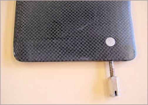
Likewise at the bottom of the fin we use a stainless steel insert through which M3 studding is placed, item INS-030. The fin is only about 4.8 mm thick here so there is no chance of using anything thicker than M3. The studding is bonded into the fin and the ballast is held in place using the long nut with a slot to allow tightening using a screwdriver.
|
|
|

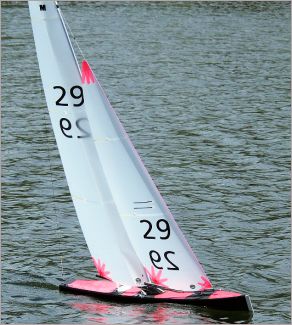
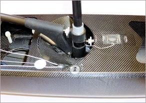 Photo by