IOM Class Gallery
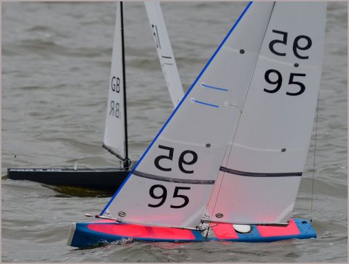
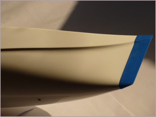
| FRAKTAL is the IOM that SAILSetc first made in early 2012. It has the rc pot accessible at deck level between the mainsheet post and the rc access hatch as standard. From early 2014 the hull form of the SAILSetc was changed slightly. The alterations are entirely at the bow and are shown in the second shot. The specification of boats from the licenced builders may vary. |
|
|
| Other builders are producing FRAKTAL in Australia, Germany, Italy and Spain. Please contact them for details of their specification. |
|
|
| The raised foredeck extends aft of the mast position and supports the mast positively at boom height. A self locking wheel adjustment allows precise mast rake control. The mainsail and headsail sheets are above deck for easy access and replacement. The headsail sheet leads via a wire fairlead near the starboard shroud point to the fairleads forward of the mast. The mainsail sheet leads through a turning block on the bulkhead and then aft to the sheet post |
|
|
| The sheet loop is tensioned under the deck using a block, spring and bowsie adjustment. The bowsie and line lead forward to the tube that connects the deck to the underside of the hull and which houses the No 1 headsail swivel line. |
|
|
|
spare |
||
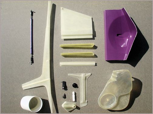
| Some of the parts used to complete a boat. The following photos indicate how some of these are used. |
|
|
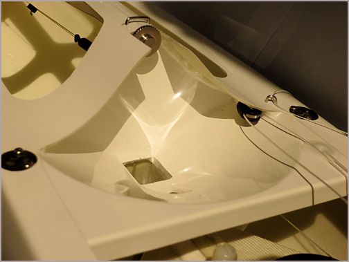
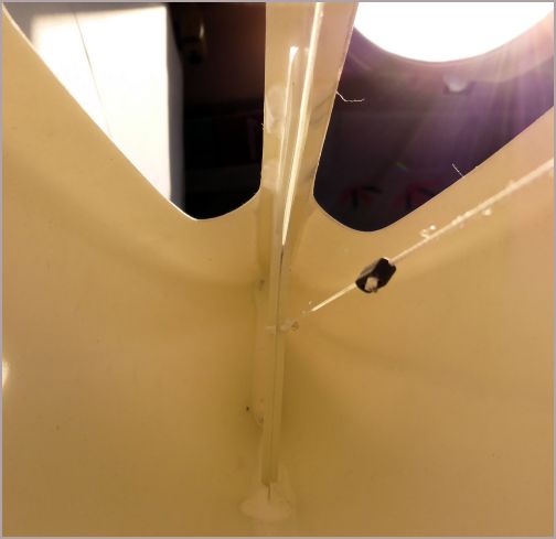
| This is the moulding that is used to join the two halves of the foredeck along the centreline. It provides several other functions at the same time. The vertical part is, in fact, a 6 mm ID tube that is bonded to the bottom of the hull. A Dyneema line from the bottom of this tube provides the swivel for the No 1 headsail. Just aft of that tube is a recess which allows the attachment points for the No 2 and No 3 headsail swivels (ball raced version 120D) to be placed low down so the headsail boom is close to the deck. The depth of the main girder provides great stiffness and helps resist large rigging loads. |
|
|
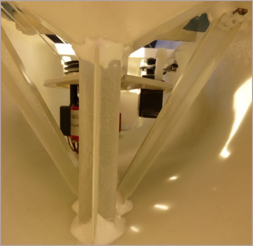
| Looking aft from the bow towards the fin box and mast tube. The diagonal connections between hull bottom next to the mast and deck edge under the shroud attachment points are specially moulded items |
|
|
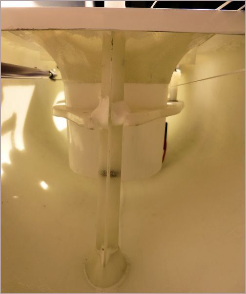
| Looking forward towards the mainsheet post and rc containment pot. The mainsheet post trunking supports the moulding that houses the rc pot and the servo and winch units. The forward end is bonded to the aft edge of the fin box for rigidity. |
|
|
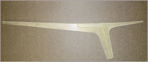
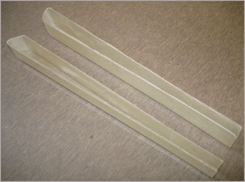
| The moulded diagonals. These are made of glass and epoxy resin but we use carbon/epoxy versions for the Marblehead, A class and Ten Rater hulls. |
|
|
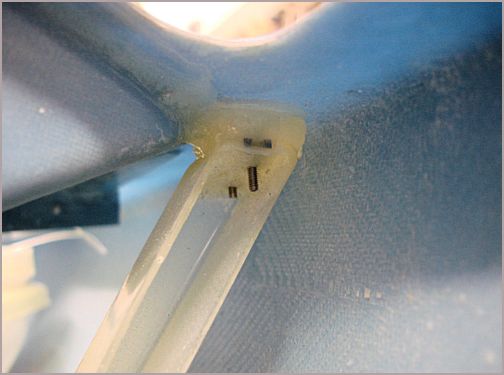
| This shot shows the connection between the upper end of the moulded diagonal and the underside of the hull/deck flange on an IOM. The diagonal is bonded in place with a stainless steel plate embedded underneath that takes the screws holding the shroud attachment plate in place. The same method is used in the Marblehead, A Class and Ten Rater. |
|
|
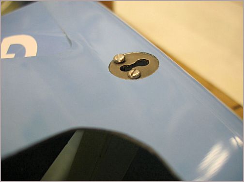
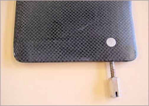
| The shroud attachment plates set flush with the deck. The plate is held down to the deck and connected directly to the diagonals with two M2 stainless steel bolts. The lower end of the rigging screw is a ball that is pushed through the larger part of the keyhole and then slid across to the other part (inboard side). Adding and removing the rig is a little quicker thanks to this refinement and, if you wish to adjust the shroud tension, you can do it without removing the rigging screw. The same method is used for the Marblehead, A Class and Ten Rater. |
|
|
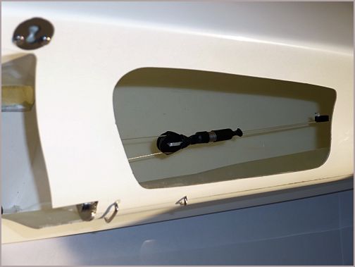
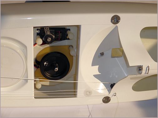
| Another shot showing the central part of the boat and the relationship between rc containment pot, rc access hatch, recess of the kicking strap and mast and shroud attachment points. The head of the fin bolt is neatly recessed to avoid catching on the mainsheet. The return line of the sheet loop is just forward of the rc access hatch on the starboard side. The servo and winch units are retained in place using quick release screws intended to be operated by finger/thumb rather than with a screwdriver. |
|
|
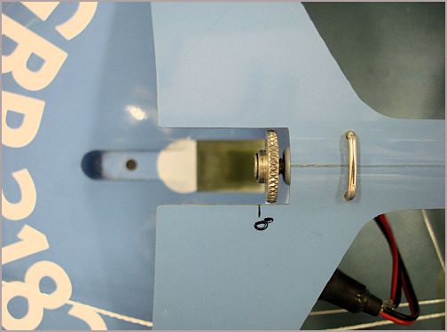
| This shot shows the mast gate area on an IOM. Our Marblehead and Ten Rater are finished in a similar way. The mast gate supports the mast positively transversely and fore and aft. The mast adjuster screw bears onto the mast and provides rake control. The threaded plastic housing into which it screws has an 'O' ring in the end (just visible) that prevents the screw from moving when not under load. The deck is marked to show where the fore side of the mast should be for vertical. Each 3 mm aft from here represents another degree of rake aft. |
|
|
|
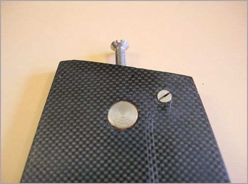
The top of the fin has a stainless steel insert bonded in place that takes the M4 stainless steel bolt used to hold the fin in place, item INS-040. Also visible at the head of the fin is the transverse M2 x 10 mm screw that we use to align the fin correctly with the hull. This permits us to correct any asymmetry.
|
|
|
|
Likewise at the bottom of the fin we use a stainless steel insert through which M3 studding is placed, item INS-030. The fin is only about 4.8 mm thick here so there is no chance of using anyhting thicker than M3. The studding is bonded into the fin and the ballast is held in place using the long nut with a slot to allow tightening using a screwdriver.
|
|
|